-
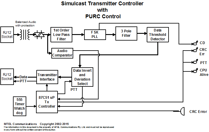
This
page describes the
Simulcast Transmitter Controller operating at Mater Hospital. This is a cut
down version of the full product.
-
The STC is a
third generation MTEL device which was developed for the CFA in Victoria in
2003. Its main function is to take link modem data and convert it to PTT and
Data for a transmitter. It has a bulk delay system which is used to time the
transmissions to provide simulcast networks.
The unit in this
configuration has the bulk delay section bypassed.
-
FSK Decoder
The received analogue signal is converted by a PLL into a digital data stream which is then decoded by a dedicated
87C51 processor to perform transmitter PTT dekey function.
The digital PLL synchronises onto the data stream and strips the
32 bit word POCSAG format into an ASCII data stream with start of
transmission, baud rate and end of transmission markers. The data stream
is checked for CRC errors and will activate the CRC error LED if there are 1
bit or more errors.
PURC Controller
The 87C51 is running
modified stcdecod.as now called stcpurc.as V1.80 Dec/2014. This version has
been modified from MTEL standard STC from 2007. The new version has PURC
control added and the digital signalling section removed. There is new
hardware (audio comparator) on the STC pcb which is required to accurately
detect PURC tones.
The software has the full
PURC 30 transmitter decoder. However it is hard coded to appear as the first
transmitter in Group 1 to 10 as there is no ability to communicate to the
processor to change the setting.
In this system only valid
2175 HLGT and Key Tones of 1950 (F1) activate the PTT, which is the end of
group one sequence.
However if Channel Change
is sent 850 Hz it will also activate the PTT. The transmitter control on
this system does not have channel change hardware outputs and so activates
PTT if channel change is sent as well.
The knock down code is
hard coded to Group 1 (1950 Hz) Transmitter 1 (1750 Hz). To knock down the
transmitter the system needs to send HLGT, then 1750 Hz then 1950 Hz.
The HLGT detection will
operate down to the smallest sequence of 120mSeconds.
-

-
The STC is a standalone device and does not require user interaction.
This LED
indicates the presence of in-band signal from the 600 ohm balanced input. In a noisy signal the LED
may flash during absence of carrier. In this case the signal should be
increased for best operation. Normally this would indicate a poor signal
from the antenna or cable.
The data
stream contains CRC information for each 32 bits of data. If the data is corrupted the CRC LED will
be on for the duration of the corruption. A Piezo will also sound whenever
the LED is ON.
This LED
has three states. When there is no signal it will flash at about 2Hertz,
indicating it is searching the data stream for
valid synchronisation data.
ON
indicates the processor has locked onto a valid high data rate paging
transmission (1200 baud). OFF indicates the processor has locked onto a valid low data
rate paging transmission (512).
The LED
will remain in this state until the data stream ceases.
This LED
activates on the detection of valid PURC tones and remains on until the end
of the data stream.
-
Grey Cable
The grey cable connects to a
receiver using a DB15 connector.
The input is limited to
600mvolts p-p. Larger signals will be distorted.
Pin 1 Blue
balanced audio in (protected on the input by diodes back
to back)
Pin 4 Blue
White balanced
audio in
Pin 9 and 10
+12 volts DC Out (This powers the receiver. It is fused with a 3 amp
fuse mounted on the PCB)
Pin 14 and 15
System Ground
Black Transmitter Cable:
Purple is Data out
connect to Pin 4 of P501
Green is Ground
connect to Pin 2 of P501
Blue is PTT
connect to Pin 1 of P501
Red and Black Alarm Cable:
Grey is Alarm Common
connect to Black cable
Red is power out
connect to +12V on P502
-
PURC Operation
of the software (from software listing for V1.80).
;*************************** PURC format
**************************************
; set up state table for tones recognition
; set up a function for x valid periods to constitute a tone.
;
;
; 01,02 ;2175,1950 normal keyup F1
; 01,0d ;2175,850 normal keyup F2
; 01, 04---0e,02 ;group 1 F1
; 01, 04---0e,03, 04---0e,02 ;group 1,2 F1
; 01, 04---0e,03, 04---0e,0f 04---0e,02 ;group 1,2,3 F1
; Tone no. ,frequency, description
; 01 2175 HLGT/LLGT
; 02 1950 KT1
; 03 1850 B KT2
; 04 1750 1
; 05 1650 2
; 06 1550 3
; 07 1450 4
; 08 1350 5
; 09 1250 6
; 0a 1150 7
; 0b 1050 8
; 0c 950 9
; 0d 850 Channel Change
; 0e 750 10
; 0f 2050 C KT3
;
;Wait at PURC FORMAT until a valid tone is detected by the interrupt.
;Must be a HLGT to begin the process_purc. Next check
;which state is the waiting for a change. There are three states. The first is
;the detection of HLGT. The next is a group tone or KT1. The third is knock down
;or KT1.
-
End of Document

