
![]()
|
|
|
|
InterHUB Client
The InterHUB Client provides a WAN connection between an existing CDAT installation and a remote site. This document is intended for operators of the CDAT system.
The InterHUB Client connection is via TCP and runs the internal CDAT product protocol. The same application runs on the local and remote sites but during installation the application is dedicated to either the originate or answer modes. The TCP connection is connected for the duration of the packet delivery i.e. each CLI packet establishes a new TCP connection.
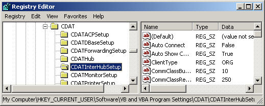
No special installation is required for the InterHUB Client if an existing installation of CDAT exists on the computer. Since the InterHUB relies completely on the existing CDAT code to exist there is no installation process as the existing CDAT application will have the correct .dll files registered for this client. The client uses the Windows registry much the same as the other CDAT clients. The current CDAT system is located in HKEY_CURRENT_USER as shown in the diagram below.
The client will automatically generate this registry if it does not exist on startup. Default values will be entered and most values will be satisfactory. Values that need changing are discussed in "Customising the Client"
The
only changes required to the settings on installation are the IP and port
address of the answer application. To make these changes, start the
application and in the top left hand corner select the Grid symbol in the
menu. In the default mode just after running the application for the first time, the Access will be be unlocked. The default password is "password" if the client access is locked without changing the password. If the access password is lost or unknown then stop the application (make notes of its settings if it was running correctly) and delete the registry entry for the client. When the application starts again the password will default allowing you access to the setup again. Now that you have access go to the InterHub Config tab and enter the correct IP and Port (socket) for the remote (Answer) end of the WAN link. Click on the correct option for the client type at the bottom of the setup and then click the save button. Both applications at the remote and local end require this information. Now that the settings are entered it is a simple matter of testing the link. Click on the test button and then select the blue disk (indicates the log) symbol in the top menu and the logging window will now appear. If you click the blue disk symbol again the window maximises to the full screen allowing you to see more log information.
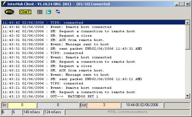
You should see logging on the originating Client as shown above. The packet transmission starts with a connection request to the remote host. If the remote end is ready there will be an event called "Remote host connected". This means the TCP link has been established between the two clients. Next the application sends a packet and waits for an acknowledgement. Once the packets are following across the WAN, some basic statistics are kept of the WAN performance. In the boxes at the bottom of the application are packet counters into the Hub Client of CLI packets from CDAT. There are also counters of CLI packets leaving the InterHub Client going across the WAN. There are also round trip delay measurements of the packet and its acknowledgement between the clients and an average of the last ten packets.
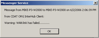
Over a period of thirty seconds there will be entries for the watchdog system which is a special packet sent between the applications to let each system know there is a valid TCP connection. If the watchdog fails a warning is generated at both ends of the link. Note that the watchdog is included in the delay measurements. If the link does fail an alarm message is sent to the operating systems network Messenger Service. An example of a LAN failure is shown below. This service is provided by W2000/XP systems and can be any sent to any valid host address. This can be an explicit IP address such as 192.168.0.1 or the machine host name such as "mike-p3-w2000" in the example below.
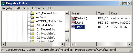
Once the link is re-established it will send a link restored message. The application will also indicate that the application has stopped and started as well. The addresses for Net Send are currently stored in the registry. The only way to edit these entries is via the registry editor. The window below shows the location of the NetSend registry and the types of values that can be entered. To add a user right click on NetSend in the regedit program and "add" a new string. name it the next numerical string such as "User3" in the case below as User 1 and 2 already exist. Then right click again to modify the new value to the desired IP address or network name. The limit is currently 9 users.
The messages sent using Messenger Service are also stored in the Event Viewer in the Control Panel, under Administrative Tools. Once your settings are correct and the application is running correctly, it is a good idea to export your registry into a .reg file from the MTEL directory and its sub-folders and contents. If the system gets a corrupted registry (usually from a poor power interruption) then the applications can be restored quite quickly and accurately by importing the .reg file.
1.5 Connecting to the Local Hub Now that the WAN output is operational, the input can be configured to connect to the Local Hub. When starting an application for the first time the registry is generally non existent and so the application will establish a registry with default values and display a set up box as shown below.
Hit the OK button and the application will start but initially will not attempt to connect to the Hub. The banner should indicate the state of the Hub connection and it should be at the intialisation state as shown below.
Normally on start-up the application will try to connect to the Hub immediately based on the previous settings, however when first started the Server Address will almost never be the correct address from default. Attempts to start with an incorrect IP address will unnecessarily frustrate the user as the application constantly attempts to talk to the Hub.
Once the setup is correct, manually start the
application from the menu as shown below When the client finally connects to the Hub, it is worth having a look at the Comms Class window again. To do this click on the "Show CommClass" menu item as shown on the left. This window provides a complete picture of the operation of the TCP connection between the Hub and the client. If you never wish to see this window, then click on the "Auto Show CommClass" until the tick is cleared. Checking this menu item will always bring the CommsClass window up when the Hub connects. Now that the application is connected to both the local Hub and the remote Hub over the WAN, it is ready to start sending CLI packets. The client should look like the window below. The banner indicating a connection to the Hub, and in the log valid watchdog packets are being correctly acknowledged by the receiving application.
|
|
|
 This will take you directly to the setup menu. The
configuration is password protected and you must correctly enter the
password before any settings can be changed.
This will take you directly to the setup menu. The
configuration is password protected and you must correctly enter the
password before any settings can be changed. 
 The
Server Port is nearly always 6000 and should be changed only if it clashes
with other applications. The Server Address is either an IP address or a
host name. The client identifier should start with an "i" and can be "i01"
to "i99".
The
Server Port is nearly always 6000 and should be changed only if it clashes
with other applications. The Server Address is either an IP address or a
host name. The client identifier should start with an "i" and can be "i01"
to "i99". 
 .
Right click in the menu. select Comms the select Connect and the Comms Class
window will appear. The banner however gives a summary of the connection
progress so simply click on the Hide button to remove the Comms Class
window.
.
Right click in the menu. select Comms the select Connect and the Comms Class
window will appear. The banner however gives a summary of the connection
progress so simply click on the Hide button to remove the Comms Class
window.