
![]()
|
|
|
|
This instruction is specific to the Serial Client application. However it assumes that this module is an addition to the existing CDAT Client suite and that the main CDAT installation process has been completed. The Serial Client is part of the original CDAT 2000 program suite. It has been upgraded to CDAT 2006 specifications. Warning: The target audience for this page is at the technician level. Changing some settings described below can result in the client failing. Settings are saved in registry so rebooting the client will not clear incorrect settings.
The Serial Client sends a serial data stream to the PremierCAD system. The Serial client is a dedicated client in that there is no configuration ability to modify the field mapping from the X25 CLI IPND incoming packet from Telstra. The format is fixed to fit in with the previous specification for the PremierCAD system. This specification was established prior to the IPND specification and therefore it can only display a subset. The PremierCAD system was not upgradeable and therefore the Serial Client was designed to modify the IPND field structure to fit. Some of the fields are concatenated to fit the PremierCAD specification.
1.3 Setting up the Serial Client The Serial Client has relatively few fields to modify.
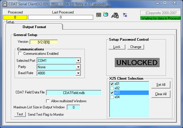
1.3.1 Serial Configuration The Communications frame is the only configuration unique to this client. The port can be disabled by the check box Communication Enabled. The com port, speed, parity and baud rate have a fixed set of parameters in which to operate.
1.3.2 General Setup Version is the revision number for the client. See the revision lists for the current version. Allow multi-sized Windows allows the output windows to be resized on the screen. CDAT Field Data File is the location of the database which defines the CLI data structure. Currently this is known as the MOLI data structure. Max Display Entries is the maximum lines displayed in the Output window which mimics the printer output. The default is 50. The upper limit is 10000 (hard coded)
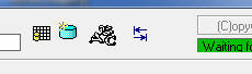
The Client has icons to jump to the 3 display modes. The grid icon is the the field layout, the blue disk is the output debug window and the ABC icon is the setup.
On installation the IP and port
address of the MTELHub is selected. To make further changes, start the
application and select the ABC symbol in the
menu. In the default mode just after running the application for the first time, the Access will be be unlocked. The default password is "password" if the client access is locked without changing the password. If the access password is lost or unknown then stop the application (make notes of its settings if it was running correctly) and delete the registry entry for the client. When the application starts again the password will default allowing you access to the setup again.
1.4.1 Serial Cabling The Serial device requires a minimum of 3 wires for correct communication with the Serial Client. The following is a description of the cable requirements for a standard 9 pin Computer port to a 25 pin Serial device connection. Pin 3 (DB9) is the transmit wire. The information is sent on this wire. Pin 2 (DB9) is the receive wire. Pin 5 (DB9) is the reference ground wire.
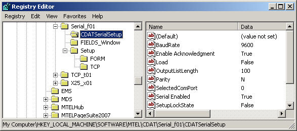
1.4.2 Registry Configuration The window below shows the registry location. In the past application development, the registry information for the client was located in HKEY_CURRENT_USER. The main reason for moving to Local Machine was some systems had multiple users and the configuration had to be setup for each user. Putting the information in Local Machine made one configuration available to all users.
1.5 Connecting to the Local Hub When starting an application for the first time the registry is generally non existent and so the application will establish a registry with default values and display a set up box as shown below.
Hit the OK button and the application will start but initially will not attempt to connect to the Hub. The banner should indicate the state of the Hub connection and it should be at the initialisation state as shown below. Normally on start-up the application will try to connect to the Hub immediately based on the previous settings, however when first started the Server Address will almost never be the correct address from default. Attempts to start with an incorrect IP address will unnecessarily frustrate the user as the application constantly attempts to talk to the Hub.
Once the setup is correct, manually start the
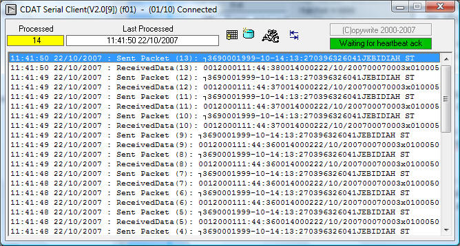
application from the menu as shown below When the client finally connects to the Hub, it is worth having a look at the Comms Class window again. To do this click on the "Show CommClass" menu item as shown on the left. This window provides a complete picture of the operation of the TCP connection between the Hub and the client. If you never wish to see this window, then click on the "Auto Show CommClass" until the tick is cleared. Checking this menu item will always bring the CommsClass window up when the Hub connects. Now that the application is connected to the local Hub it is ready to start sending CLI packets. The client should look like the window below. The banner indicating a connection to the Hub, and in the log valid packets are being correctly acknowledged by the receiving application.
1.6 Serial Field structure The fields are joined by the following function; index is the field number.
index = 102 'Job
reference
1.7 Client Log All clients create and run a text log. The log is always located in a sub-directory called .\LOGS. The Serial Client log file is called serialclient.log an example is shown below.
File : serialclient.log
|
|
|
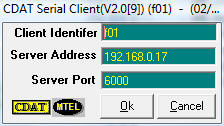 The
Server Port is nearly always 6000 and should be changed only if it clashes
with other applications. The Server Address is either an IP address or a
host name. The client identifier should start with an "f" and can be "f01"
to "f99".
The
Server Port is nearly always 6000 and should be changed only if it clashes
with other applications. The Server Address is either an IP address or a
host name. The client identifier should start with an "f" and can be "f01"
to "f99". 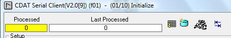
 .
Right click in the menu. select Comms the select Connect and the Comms Class
window will appear. The banner however gives a summary of the connection
progress so simply click on the Hide button to remove the Comms Class
window.
.
Right click in the menu. select Comms the select Connect and the Comms Class
window will appear. The banner however gives a summary of the connection
progress so simply click on the Hide button to remove the Comms Class
window.