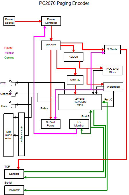
The M2MPaging PC2070 contains several components to
ensure the integrity and stability of the encoder. It was designed to
operate in remote locations and be capable of rebooting remotely or when the
communications to the input fail.
There are;
- Switch-mode Power Supplies
- Data Monitoring Circuits
- Processor
- POCSAG clock
- I/O circuits

Power Supplies:
The unit is powered by 5 individual switch mode
power supplies to provide isolation and control over sub systems.
The main power into the PC2070 is controlled by an
overarching data timer of approximately 10 minutes. If there is no data
packets being received on the LANPORT the power controller shuts down power
to the entire board.
The processor has the ability to reset the LANPORT
power independently of this feature. If the software detects any anomalies in
its operation, it can reset itself by the watchdog circuits or under command
from the LANPORT.
Data Monitoring:
The unit monitors the received serial data on the
board side of the LANPORT.
This monitor is locked out from operating inside the
first 40 seconds of power up to allow the Comms to be established before
monitoring can be started.
Processor:
The unit processor is a ZWorld module running on
512K flash memory and 512k RAM.
The program is written in C and uses interrupts to
run the POCSAG generation as well as protocol processing.
Its unique capability is its ability to generate
POCSAG code and buffer messages efficiently while transmitting. More
importantly it can inject priority messages into a batch even if its running
on a different baud rate.
The processor also runs a command protocol to allow
it to run a debug trace while still running.
POCSAG Clock:
The clock is a proprietary design to keep the output
jitter to < 1uSecond. This allows the batching to operate well into 30
second batches. The batch size is then solely dependent on the stability of
the pager clock.
I/O Circuits:
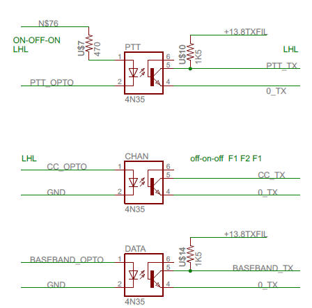
The POCSAG output has a baseband and PTT or RTS
style of opto-coupled circuits.
The TMP protocol has the ability to select different
zones or channels.
The channel capability has been restricted to 2 channels on this
board. The output could be used to change frequency on a transmitter or select
or toggle an independent
device.

Communication Ports:
The TCP input is the Lantronix LANPORT. This has
industry standard Web interface which can be configured to variety of
different types of operation. This device has proven to be very reliable for
24/7/operation.
The default settings operate well over wired LAN
networks however it needs modification to run over wireless TCP networks and
wired WAN networks.
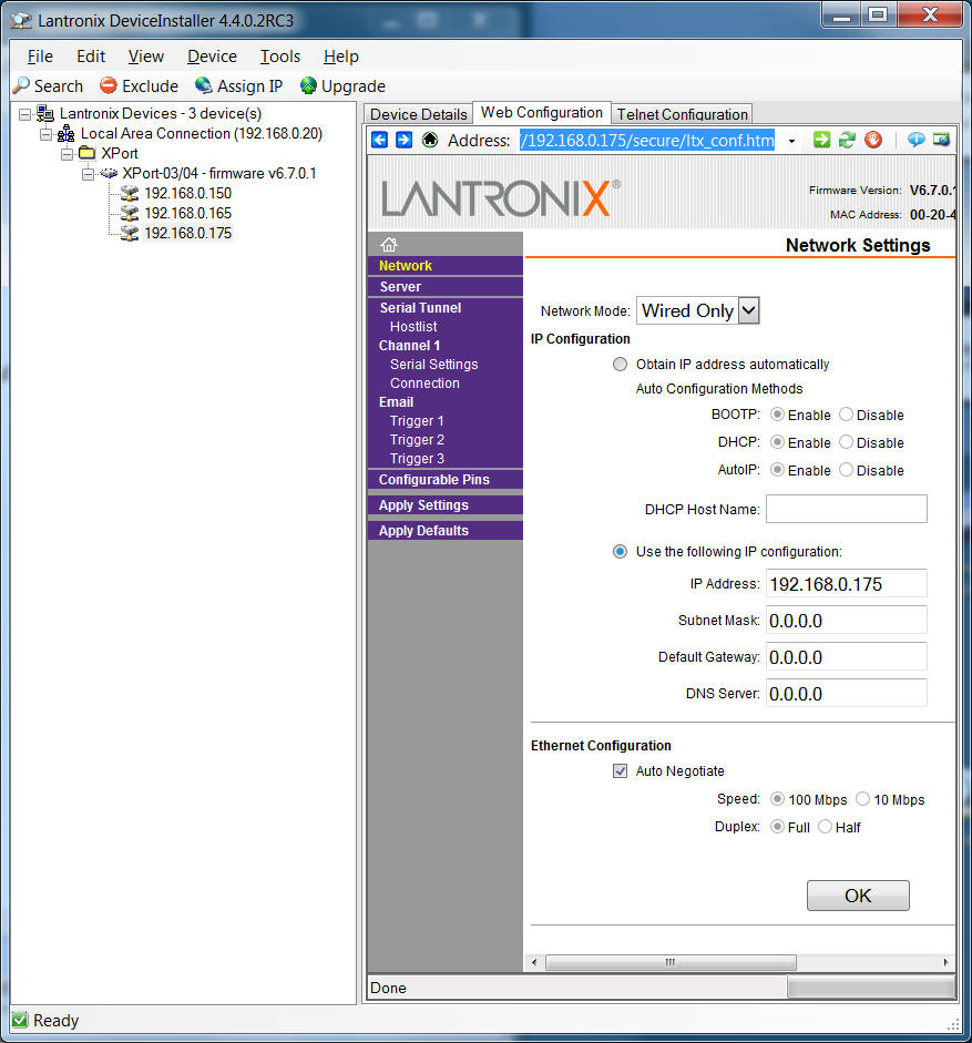
The LANPORT is configured with the Lantronix Device
Installer.
The current model is XPort-05 and requires
DeviceInstaller V4.4.0.2RC3 as a minimum level version.
The diagram below is a typical DeviceInstaller
session.


