
![]()
|
|
|
|
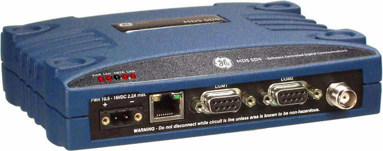
MDS ReceiverThe receiver MDS 9710C is supplied by Wireless Data Solutions and has the following specifications.
TECHNICAL REFERENCE MDS 4710A/C/M and 9710A/C/M/T Transceivers’ Specifications GENERAL Frequency Range*: MDS 4710A/C/M MDS 9710A/C/M/T 330–512 MHz 800–960 MHz * w/One or more sub-bands as permitted by regulatory agencies Frequency Stability: ±1.5 ppm RECEIVER Maximum Usable Sensitivity: MDS x710A/T: –110 dBm at 1x10⁻⁶ BER MDS x710C: –105 dBm at 1x10⁻⁶ BER MDS x710M: –106 dBm at 1x10⁻⁶ BER Co-Channel Rejection: MDS x710A/M/T: –12 dB MDS x710C: –18 dB Adjacent-Channel Selectivity: 60 dB Spurious-Response Rejection: 70 dB Intermodulation Response Rejection: 65 dB Spurious Conducted Emissions: –57 dBm (9 kHz to 1 GHz) –47 dBm (1 GHz to 12.75 GHz) Bandwidth: MDS x710A/M/T: 12.5 kHz MDS x710C: 25 kHz DATA CHARACTERISTICS Signaling Type: EIA/RS-232; DB-25 Female connector Data Interface Rates: 1200–19200 bps, asynchronous Data Latency: 10 ms maximum PRIMARY POWER Voltage: 13.8 Vdc Nominal (10.5 to 16 Vdc) Negative-Ground Systems Only TX Supply Current: 2.5 Amps (Maximum) @ 5 Watts RF Output RX Supply Current: Operational—125 mA, Nominal Standby (sleep)—15 mA, Nominal Power Connector: 2-Pin polarized & locking connector Fuse: 4-Amp Thermal Fuse, Self-Resetting, Internal (Remove primary power to reset) ENVIRONMENTAL Humidity: 95% at 40 degrees C (104°F), non-condensing Temperature Range: –30 to 60 degrees C (–22°F to +140°F) Weight: 1.0 kilograms Case: Die-cast Aluminum
Analog Operation of the Transceiver The transceiver is designed for full digital modulation, while offering analog support to those systems that require it. Operation is compatible with the MDS x710 family products, but some SD radio-specific command configuration and wiring may necessary based on differences in SD hardware. This section describes the connection using the radio in analog service. Physical Interface The physical interface for analog operation utilizes pins on radio's COM1 (management) connector. This connector is multiplexed with the serial data lines used for software commands. The applicable pins of the DB-9 are as follows: • Pin 8—Receive Audio (-20dbm to 0dbm, as set by RXLEVEL command) • Pin 4—Transmit Audio (-20dbm to 0dbm, as set by TXLEVEL command) • Pin 6—Push-to-Talk (3v TTL, 5v tolerant) • Pin 5—Ground (negative supply potential)
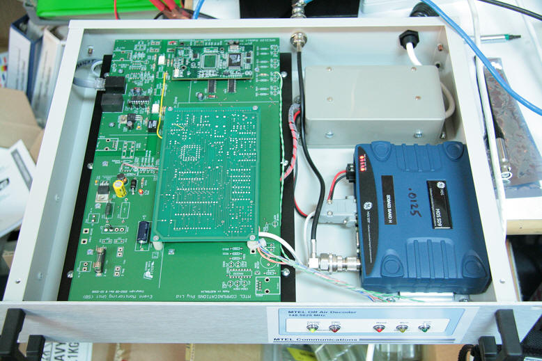
The MDS in the OAD The diagram below shows the location of the MDS and internal connections.
|
|
|