-
This
page describes the Low Power Paging Transmitter for use in the “3 Paging
Networks” through out Australia.
-
The Low
Power Paging Transmitter is a collection of three devices to produce a
paging product with commercial paging capability. This unit will only
operate in metropolitan centre's where terrestrial based commercial networks
exist. At this point in time there is only one paging carrier left in
Australia.
The unit
acts as a repeater operating in the same manner as the higher power
commercial systems, providing simulcast quality transmissions inside or
adjacent to existing paging networks.
The unit
is intended to provide fill in cover in low signal strength commercial
coverage. It is also intended to operate in areas where some commercial
signal may overlap the coverage from this unit.
The units
primary purpose is to provide seamless coverage in these overlap areas, such
that the pager is unaware of the overlap and the coverage does not interfere
with existing commercial operation.
Unit block diagram of operation
-
The unit
contains an MDS link receiver, MTEL Simulcast Controller and a WiPath paging
transmitter.
The link
receiver operates in the 860MHz range. It is intended to receive the
broadcast commercial link signal from the paging carrier. The information is
transmitted in analogue modem tones at a variable bit rate. All transmitters
in the same network receive this signal and translate it to the baseband
frequency for the pagers.
The link
receiver frequency of operation is dependent on the commercial paging
baseband channel and will also vary between metropolitan cities. MTEL
Communications should always be consulted if the unit is to be operated in a
different location to the default settings.
Operating
this unit in other than the original designed location will constitute an
illegal transmission as its operation is licensed and subject to the
operational requirements of the Australian Communications and Media
Authority.
Currently
there are two paging networks operating nationally, “3 Paging F1” on
148.5625MHz and “3 Paging F2” on 148.6375MHz. The broadcast link frequencies
for these networks are different in every capital city.
This unit
operates on only one paging channel. In Brisbane there are two main paging
channels. The units have been configured for the following link frequencies.
-
The
Simulcast Controller provides all the signaling, modem control, bulk delay
and error detection for the paging data stream. The signal from the receiver
is first processed by the FSK PLL which converts modem tones to data. The
data stream is then subjected to a delay before being sent to the
transmitter.
This
sub-system provides the synchronisation to the commercial carrier systems.
It is accurate to approximately 10 microseconds. The synchronisation of the
data stream is extremely important. If the data is not synchronized the
overlap coverage from the commercial network and this unit will be
corrupted. This will cause the pager to lose synchronisation on the networks
for as much as 30 seconds.
The
synchronisation is dependent of the physical location of the unit in respect
to the commercial carrier. This unit has been timed to operate within 10
kilometers of the Brisbane CBD. Operation outside this geographical area
will produce corruption.
As well as controlling
the data stream, the processor maintains a CRC check of the data. The paging
signal operates on 32bit word boundaries each with its own CRC information.
The processor checks each word and will indicate any errors. (see Unit
Operation)
The MTEL
Station Controller is designed and manufactured by MTEL Communications Pty
Ltd.
Input:
RJ12
Connector
600 ohm
balanced audio level (0dbm max -30dbm min)
Bell 202
modem tones.
Decoder:
POCSAG
Paging Protocol
Bulk
Delay:
Fixed
delay 1.28ms (link P202)
Variable
delay 3.840ms (software selectable to 10uSeconds)
Total
delay 5.12ms
Transmitter Interface:
RJ12
Connector
PTT TTL Open Collector. (Active Low)
Data TTL Open Collector.
-
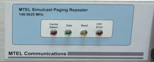
The front
panel contains 4 LEDs indicating the state of operation.
On power
up the unit will take approximately 15 seconds to begin generating output
power.
This LED
indicates the presence of the link broadcast 860MHz signal of greater than
-115dbm. Ideally this level should be greater than -100dbm for best
operation. When the Carrier Detect activates, the PTT is enabled on the
output transmitter, producing the baseband paging carrier. However because
it is a digital transmission the carrier will come at the center frequency
+4.5KHz or -4.5KHz.
This LED
reflects the data output of the FSK modem. It will flash at different rates
dependent on the baud rate of the paging signal. Flashing indicates data.
Always ON or OFF indicates no data.
This LED
has three states. When there is no signal it will flash at about 5Hertz,
indicating it is searching the data stream (indicated by the Data LED) for
valid synchronisation data.
ON
indicates the processor has locked onto a valid high data rate paging
transmission. OFF indicates the processor has locked onto a valid low data
rate paging transmission.
The LED
will remain in this state until the data stream ceases.
The data
stream contains CRC information. If the data is corrupted the CRC LED will
be on for the duration of the corruption. A Piezo will also sound whenever
the LED is ON.
If the
CRC indication activates it will usually be a result of lack of signal on
the broadcast link or it may indicate interference on the link receiver.
The
picture below is for “3 Paging F1” unit.
-
The rear
panel contains the 240 volt input and two RF N Type connectors. The left
hand side connector is the link input. The right is the output transmitter.

-
Testing
the unit
The unit can be bench
tested by inserting a modulated carrier on the link frequency at a level of
-80dbm. The transmitter output should be 1 watt at the base frequency
+4.5KHz
or -4.5KHz.
It will
not transmit at the carrier frequency as the output is a binary digital
transmitter and will be at either the preset + or – deviation of the carrier
frequency.
To check
the transmitter deviation, set the modulated signal to 1200Hz or 2200Hz and
the deviation should change accordingly.
When the unit is
installed in the field, the link signal from the antenna should be at a
level > -100dbm. If the level is to low the bit jitter introduced into the
data stream will be too excessive for reliable operation.
Once the unit is
installed the coverage area should be tested for reliable operation.
The coverage overlap
area must also be checked. The best equipment for this test is a POCSAG bit
error meter on the paging frequency. Passing through the overlap should
produce very few errors if the synchronisation has been correctly set.
A bare minimum test
should be the continued lock of the bit error meter during the transition of
the coverage area.