|
The PC190 is a 148MHz 25 watt paging system which is solar powered and has a circuit
switched cellphone as the input device. The input is the standard PET protocol
and it accesses the onboard database for pager number verification.
1. General Description
The PC190 is a solar powered and contains the minimal modules for a
paging system.
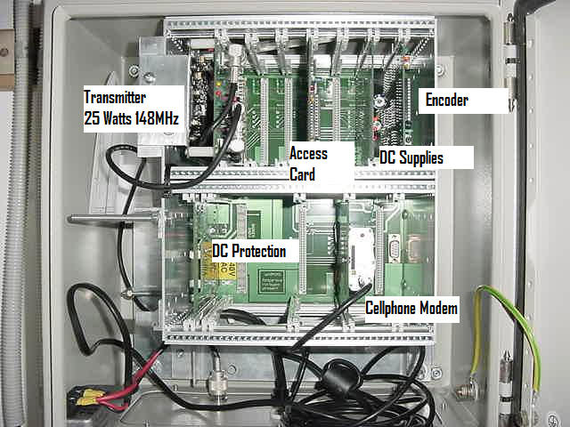
The picture below displays the system and the cards in their correct
location. The diagram below shows the older GSM style of modem. All systems
now are equipped with the blue Modmax 3G modems.
Note that the Encoder is always located in the top
row right hand slot. The DC card can be located in any slot. The Access card
is normally located in slot four in the top row. The modem is located in the
middle slot in the bottom row.
The RF Interface module is always located in the top
left slot so as to be mated with the chassis frame which is a heat sink for
the RF module. Usually two screws are secure the module to the chassis.
2. Card Descriptions
PC 201 DC Supplies
The DC supply card has three red leds. These indicate the -12 (top) , +5
(middle) , and -12 (bottom) volt supplies are operating within limits. If
any of these are not on then the supply is not operating or below acceptable
operating level.
PC204 Encoder
The Encoder card has three leds. The middle is the Processor Alive led.
It should flash about once a second. When the Encoder is sending messages
all three leds come on and the top data led will pulse at the data rate. The
Encoder also emits an audible tone when sending messages.
PC203 Access
The Access Card is the gateway processor and interfaces to the modem.
When the cellphone or the Access card are in communication the middle led
will pulse with the data flow.
On power up, the Access card sends a signal to the cellphone card to
power down the cellphone. The power is restored after 5 seconds. Then 10
seconds later the Access card will send initialisation strings to the
cellphone. The red center led will pulse on the Access card when this
occurs. Eight strings are sent about every 2 seconds. At the completion the
cellphone will power down again from the last string which is a reset
command to tell the modem to reset. If the modem is working correctly it
will power cycle at this point.
At the completion of the eight strings the Access card will send a start
up warning message to the Encoder card. At this point the Encoder will emit
an audible tone.
Cellphone
The cellphone is a blue Modmax and when idle will have two red leds on.
The first and the fourth from front to back. This indicated the cellphone is
registered to the Telstra network. If the front led flashes the signal into
the cellphone is poor or non existent.
When the cellphone is connected in circuit switch mode on an incoming
call the two front leds will be on.
PC2022 DC Protection
This card simply holds the diode protection and fuses for the raw DC
solar supply. A red (raw DC supply) and yellow (fused power) led should be
on indicating the fuse is OK.
Elpro Transmitter 25 Watts and PC205 RF
Interface card
The PC205 Transmitter interface card has three leds, Yellow (forward power OK), red (VSWR is
OK), green (data). The red and yellow are normally on and the green flashes
about once a second. When the Encoder starts a transmission the red and
yellow leds should go out and the green will pulsate at the data rate.
If the yellow stays on and the red off, the transmitter is generating low
power, but the antenna is OK.
if the red stays on and the yellow off, there is a VSWR problem.
If both stay on there is a VSWR fault, but the forward power is
indication maybe compromised.
3. Testing the system
The Transmitter can be tested using the PTT button on the Encoder card.
GREAT Care should be taken
when using this test as the transmitter does not have a PTT timeout function
and it will remain on forever if left in the test mode.
To activate the transmitter for checking VSWR and power, simply press the
PTT button. The button is then pressed four more time to return it back to
the PTT OFF state. During these presses the button sends data at different
baud rates and this is used for advanced diagnostics.
At 25 watts the transmitter generates a lot of heat. It is not designed
for continuous duty, however the transmitter is reasonably hardy and it is
important not to transmit into an open circuit, or into a load for periods
not greater than 30 seconds on, and a cooling off time of four times the on
time.
4. Intelimax
Version
The latest PC190 will contain a variation to the
circuit switched cellphone modem. It now uses the wireless broad band
product from Telstra.
The Intelimax is the replacement cellphone and the
PC203 Access card is replaced with the PC2060 which is a major upgrade to
the previous Access card functionality.
The PC2060 provides message
queuing and simultaneous transmission and message packet reception from the
WBB modem. In addition it is capable of sending diagnostic information back
to the MTELGateway about the power supply, battery, RF VSWR, modem RSSI as
well as time, configuration download and logging functions.
The Intelimax modem
interface card is also capable of powering down the modem if there is an
absence of data from the Gateway more than 10 minutes.
The packet protocol uses
TNPP which is CRC protected compared to the older TAP/PET protocol of the
PC203 Card.
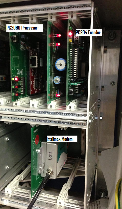
PC2060 Processor
The PC2060 Card is the
gateway processor and interfaces to the modem. When the cellphone or the
Access card are in communication the middle LED pair will pulse with the
data flow.
The top LED pair are the
bus data and should always be pulsing. The bottom pair of LEDs are for
diagnostic information only.
On power up, the PC2060
card sends a signal to the cellphone card to power down the cellphone. The
power is restored after about 5 seconds.
At the completion of the
eight strings the Access card will send a start up warning message to the
Encoder card. At this point the Encoder will emit an audible tone.
Intelimax Cellphone
The cellphone is a silver
box Intelimax and when idle will have two red LEDs on. The first is the
power and the second is activity. The first should always be on indicates
the cellphone is registered to the Telstra network. If the front LED flashes
the signal into the cellphone is poor or non existent.
When the cellphone is
connected and has a TCP connection the RSSI/Data LED will flash.
It takes up to 2 minutes
for the Intelimax to register and for the TCP connection to be established.
During this time the PC2060 interrogates the modem to determine the
RSSI level and the state of connection. The system will page this
information out in a diagnostic paging message during this process.
Once the TCP connection has
been established the middle green and red LEDs on the PC2060 will
pulse together as packets are sent into the system. It should pulse as much
as once every 10 seconds.
|