1. General Description
The PC2016 is the main alarm card for the picocell
systems. Current Revision is Hardware PC2016 Rev C. Firmware V1.01 March 2000.
Checksum 8787.
It has 3 independent and opto isolated channels. Each
channel is assigned a canned message which can be sent to one or more pagers.
PC2016 3 Channel 12-24Volts
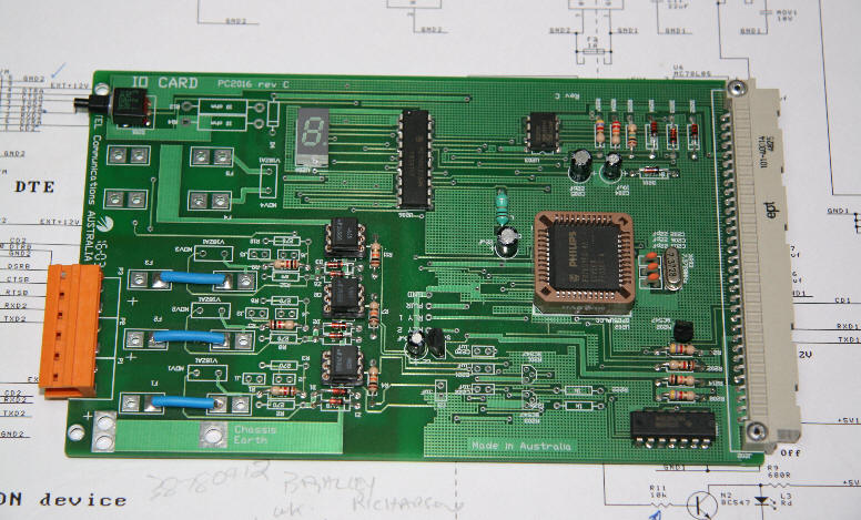
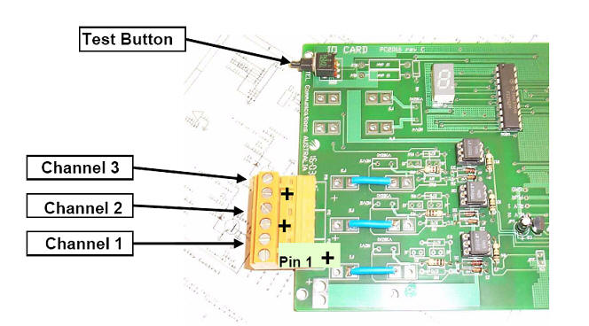
There are two versions of this card. The older style is
a fuse protected contact closure, the newer with a orange connector is a 12-24
volt input.
The card sends status information to the PC203 Access
card over the SAS bus. As well as the 3 channels the push button status on the
front of the card is also sent in the status packet.
The functionality of the PC2016 is solely determined by
the software running in the PC203 Access card. Like all other auxiliary function
cards the function of the PC2016 is simply to report the status of the 3
channels and the push button. The card itself does not generate messages.
The card may be inserted or removed at any time. However
on inserting the PC2016 card the PC203 will receive status information
immediately and will act on the state of the alarms. It is best to connect the
contact alarms to the front connector and make sure they are in the quiescent
state before plugging in the PC2016.
2.
Alarm Configuration
The alarm operation is defined in the PC203 card. The
configuration is set up in the "picocell pstn data.mdb" database which is
used to compile the executable code and database information for the PC203 card.
The SiteAlarm table defines the settings which are used to determine the
canned messaging of the alarm card. The example below are the definitions for
the canned messages attached to the alarm channels.
SiteAlarm
|
CustomerID |
Picocell_SiteID |
Alarm_Name |
SeqNo |
Alarm_Text |
|
QFRA |
RAVENSHOE_NG |
_ACT_ALARMS: |
1 |
db 'AFA Fire alarm paging now operational',0dh,0h |
|
QFRA |
RAVENSHOE_NG |
_ALARM_1: |
1 |
db 'FIRE ALARM RAVENSHOE Selcal',0dh,0h |
|
QFRA |
RAVENSHOE_NG |
_ALARM_1_reset: |
1 |
|
|
QFRA |
RAVENSHOE_NG |
_ALARM_2: |
1 |
|
|
QFRA |
RAVENSHOE_NG |
_ALARM_2_reset: |
1 |
|
|
QFRA |
RAVENSHOE_NG |
_ALARM_3: |
1 |
|
|
QFRA |
RAVENSHOE_NG |
_ALARM_3_reset: |
1 |
|
|
QFRA |
RAVENSHOE_NG |
_ALARM_LL_pager: |
1 |
|
|
QFRA |
RAVENSHOE_NG |
_ALARM1_pager: |
1 |
81257 |
|
QFRA |
RAVENSHOE_NG |
_ALARM2_pager: |
1 |
|
|
QFRA |
RAVENSHOE_NG |
_ALARM3_pager: |
1 |
|
The SiteFG table defines the settings which are
used to determine the operation of the alarm card. The example below are the
definitions for the alarm timings attached to the alarm channels.
SiteFG
|
Picocell_SiteID |
SeqNo |
String_Name |
String_Text |
Description |
|
RAVENSHOE_NG |
5 |
ALARM_LEVEL equ |
01h |
01h means level
based alarms. 0h means any toggle creates a message |
|
RAVENSHOE_NG |
6 |
ALARM_MASK equ |
01h |
0h to 07h . Each
bit turns on the alarm. 01h turns on channel 1. 07 turns all three on. |
|
RAVENSHOE_NG |
7 |
ALARM_ACTIVE_LO equ |
01h |
01h means loss
of 12 volts is active or closed circuit is active |
|
RAVENSHOE_NG |
8 |
ALARM_PAGE_RESET equ |
0h |
a 01h means a
message is sent if the alarm is reset. |
|
RAVENSHOE_NG |
9 |
ALRM_RPT equ |
0h |
a 01h means the
message will be repeated if continued in active state |
|
RAVENSHOE_NG |
14 |
ALARM_DISABLE equ |
0h |
a 01h disables
all alarms |
|
RAVENSHOE_NG |
33 |
c_ALARM_FILTER_1 equ |
030h |
this is the
delay time before activating the alarm. 030h is about one second |
|
RAVENSHOE_NG |
34 |
c_ALARM_FILTER_2 equ |
0300h |
this is the
delay time before activating the alarm. 0300h is about 60 seconds |
|
RAVENSHOE_NG |
35 |
c_ALARM_FILTER_3 equ |
0300h |
this is the
delay time before activating the alarm |
|
RAVENSHOE_NG |
36 |
c_ALARM_RPT equ |
0h |
this is the
repeat time delay |
The Alarm_Level should be 01h in most systems.
This means it is a logic level based alarm. That is a logic level determines the
active state of the alarm.
The Alarm_Mask is a bit mask where a logic 1
activates the alarm channel.
- 01h is channel 1
- 02h is channel 2
- 04h is channel 3
The Alarm_Active_Lo is the polarity of the active
state for the alarm. This state has different meanings for the two cards.
The segment display shows the state of the alarm.
The polarity is governed by the database entry.
Voltage Input Cards: (Orange connector)
Loss of Voltage the segment goes out. Connect
12-24 Volts and the segment lights up.
A 01h means the active input for voltage based cards is
the loss of voltage and the segment goes out.
A 0h means conversely, the active state is
the application of 12-24Volts.
Contact Closure Cards: (Grey
or Black connector)
Close the contact the segment goes out. Open the
contact the segment lights up.
A 01h means the active input is a closed contact and the segment goes out.
A 0h means conversely, the active state is
the opening of the contact.
The polarity state of the channel can be visually
checked on the 8 segment display. If the Alarm_Active_Lo is set to 01h then the
active condition is when the segment goes out. This is a fail safe condition.
The eight segment display alarm position is shown in the
diagram below..
2.
Connecting the PC2016
The diagram below shows the connection to the
12-24volt model. Pins 1,3, and 5 are the positive inputs.
|