
![]()
|
|
|
|
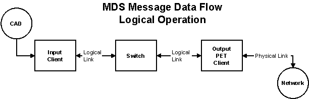
The MDS is a modular group of programs designed to deliver messages from CAD based systems to related networks for the appropriate messaging device. It is designed to provide back up and redundancy from end to end to increase the success of delivery. It also provides a universal message delivery system regardless of the way in which the message is delivered, the type of end user device receiving the message and how such devices are grouped together. The diagram above shows the basic end to end modules for a single method of delivery. It has been simplified to assist in the description of the complete system. The rest of this page relates to the reliability of the links between these modules and how they are configured to provide the fastest possible level of delivery in normal and error conditions.
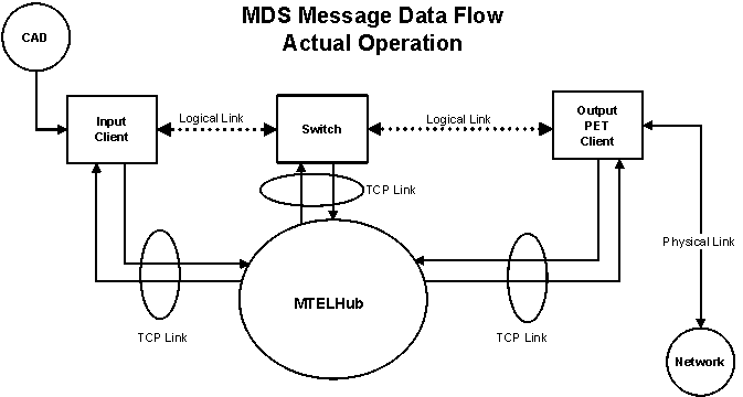
The weakest link in the end to end system are the logical links between the modules. These links are implemented in TCP so that the modules can operate over a LAN or WAN as well as if they all resided on a local workstation. There are also physical links to the networks from the clients however they are not discussed in any detail in this page. The modules intercommunicate over the TCP links using a module called MTELHub. The Hub is simply a sophisticated store and forward switch with built in switching capability embedded into the TCP packeting information. Its task is to delivery packets between the clients and if the link is broken it can store the messages and delivery them to the client when the connection is restored. The logical link between the clients is implemented as a series of TCP links which buffer and forward the packets to the logical client. There are buffers on the exit and entry of all TCP packets as shown in the diagram below.
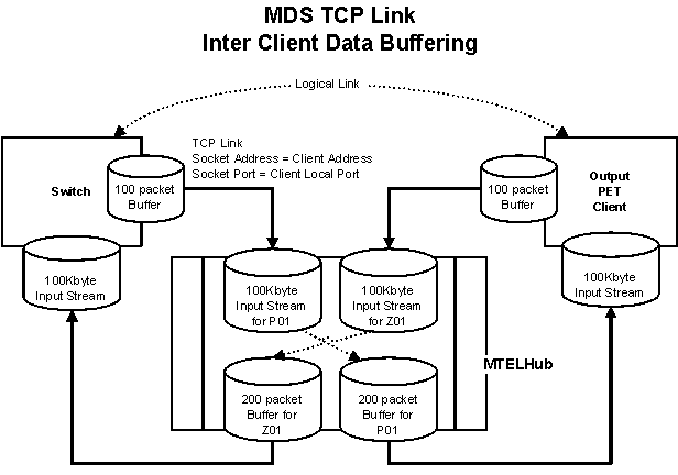
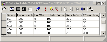
Hub Buffer configuration: All TCP input processing has been set to a 100k byte buffer. The Hub processes the string in 100 milliseconds time slices. The hub allocates an input buffer for each client. The clients have just a single input buffer. The size of the output buffer is determined by the MDSTCPClient table RemoteBuffer field. This information is passed to the Hub when the client first connects to the Hub. HubMaxBuffer field is not used in this application. On the TCP output the Hub determines where the packet is to be sent and then stores the packet in an output buffer. If the buffer contains more than one packet it will continue until either the input or output buffers are empty.
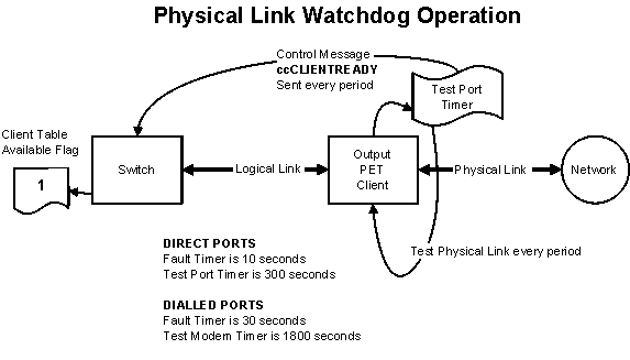
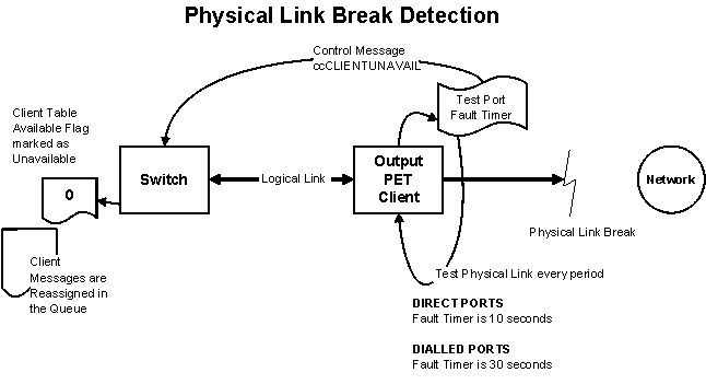
Physical Link testing: All output modules monitor the network to which they are connected. If the network is detected as failing then a message is sent to the switch in the form of a control packet which tells the Switch to disable that module client. Direct based ports are tested more frequently then dialled up networks. Even though the physical link is broken the module continues to test the network for normal operation. Once the module detects the network is operational again then the Switch receives a control packet indicating the link is valid and the Switch marks the availability flag in the database ready to receive message packets again.
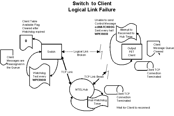
In the diagram below the physical link is broken and it indicates to the Switch to reallocate messages back into the input queue for delivery to another redundant or backup module.
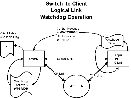
Logical Link testing: All input and output modules have a logical connection to the Switch Module. The Switch has a bi-directional logical link with all output modules and a uni-directional link with input modules. A logical link must be reliably maintained with all modules so that messages are delivered as quickly as possible. These links use a watchdog technique to decide if the link is valid or not. The advantage is that the TCP traffic can be kept to a minimum, the disadvantage being it takes additional time to detect logical link failures. The watchdog technique requires a regular poll from a client to the Switch to indicate the link is valid. If a watchdog is not received in the designated period then a fault condition is deemed to have occurred. In general, two watchdog packets are sent by the client to the switch during any one watchdog period.
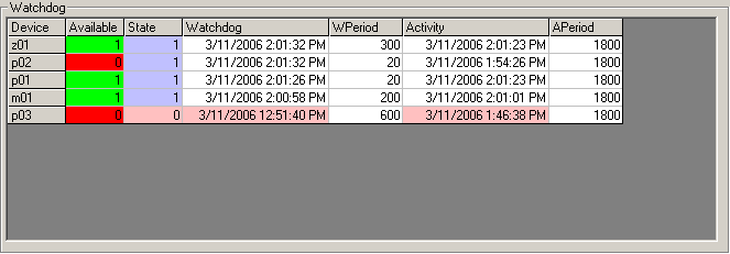
Client to Switch Logical Watchdog Timer: The Client reads the WPERIOD field in the MDSClient table value, divides it by two and generates a system Watchdog packet destined for the Switch. This packet is seamlessly passed through Hub to its destination and is processed by the Switch which updates the Watchdog Table in the Watchdog tab as shown below. The main reason for this timer is to decide what clients are available for message distribution. It there are any breaks in the connection to the eventual network then the client will become unavailable and messages will be diverted to either redundant or backup networks.
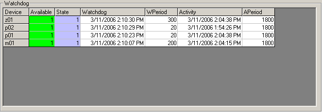
Switch detects a Logical break: When the Switch detects a watchdog expiration it will perform two tasks. The first is to make the client unavailable in the MDSClient table. The second task is to break the logical connection to the client and wait for a reconnection from the client. The test is performed every 5 seconds and this is how often the Watchdog grid is updated. If messages are being processed at the time they will be reassigned back to the input queues. The diagram below indicates p02 and p03 are unavailable. P03 however has a Watchdog failure indicated by the pink colour in the time field. P02 is unavailable as the physical link has failed at this time.
P02 above has a WPERIOD of only 20 seconds. In this case p01 and p02 are directly connected output devices. They can deliver messages to the networks in single seconds. Setting the watchdog to a small value speeds up the fall back to a backup or redundant output client. Dialled output devices typically require tens of seconds to deliver messages and so the WPERIOD should be set to a higher value. Note that this Logical link timer WPERIOD is independent of the TCP Timer described below.
Hub TCP Watchdog Timer: The Hub watchdog test timer runs every 5 seconds. It tests all members at the same time for timer expiration which is is set by the CCWatchdog in MDSTCPClient table. The table content is read by the client and on connection to the Hub, it passes this value as well as the rest of the table values for that client to the Hub. All values for the client are stored in memory and only last the life of the connection. The table value can be viewed in the System State Tab on the Hub in the field Watchdog. The time the last watchdog was received is in the field LastWDog. If the value is changed the Client must be restarted to read the new value and pass it on to the Hub when connected. If the timer ever expires for the Watchdog the TCP connection is Killed immediately if it exists. If the connection has failed the Logical link is cancelled by the Kill command. Client TCP Watchdog Timer: The Client reads the CCWatchdog value divides it by two and generates a system Watchdog packet destined for the Hub only. So a system packet is sent every half CCWatchdog period to reset the timer in the Hub. The test is only sent if the Client is flagged as being connected to the Hub i.e. it appears to have a logical connection to the Hub. Client Detects a TCP Failure: In general Input type clients send NewMessage packets, and Output clients send Update packets. In either case if the TCP link fails it will be detected when the clients attempt t send packets. In this case the client will call KillConnection. This breaks the logical link to the Hub and attempts to close the existing socket. Once the logical link is disconnected the client will attempt to reconnect to the Hub using the parameters from the MDSTCPClient table as shown above.
|
|
|